
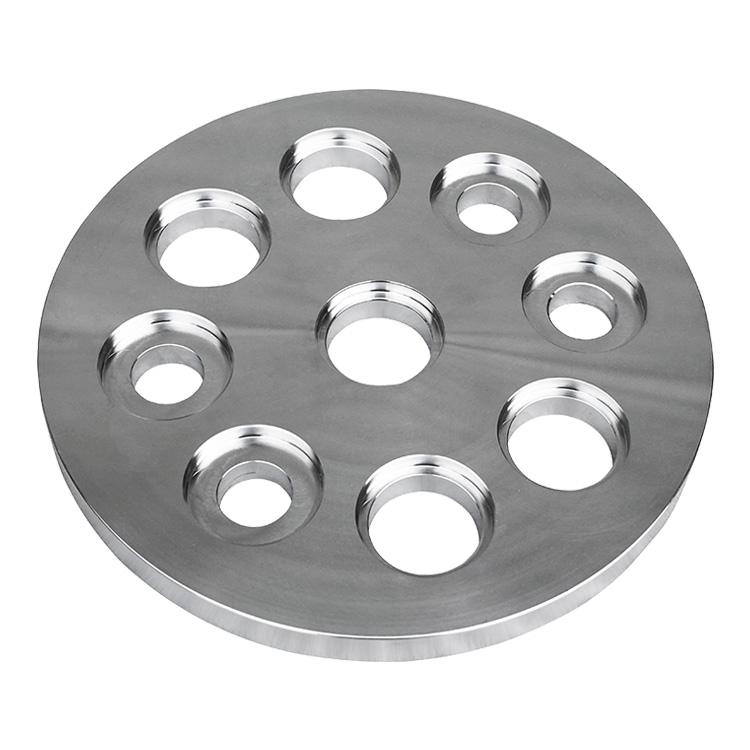
In industrial piping and thermal transfer applications, the Industrial Standard Flange for Heat Exchanger Systems plays a critical role in ensuring secure, leak-resistant, and serviceable connections. Heat exchangers are used across power generation, chemical processing, oil and gas, HVAC, marine, food processing, and many other industries. In these systems, flanges are essential components that connect pipes, shells, heads, nozzles, and associated equipment while allowing safe assembly, disassembly, inspection, cleaning, maintenance, and replacement.
For engineers, buyers, and project specifiers, understanding the structure, standards, materials, pressure ratings, dimensions, and applications of a heat exchanger flange is essential. The right flange selection can improve reliability, reduce downtime, support long-term performance, and ensure compliance with industrial standards. This guide provides a detailed overview of the Industrial Standard Flange for Heat Exchanger Systems, including definitions, benefits, common types, specifications, size references, material options, and selection considerations.
An industrial standard flange for heat exchanger systems is a standardized mechanical connector used to join heat exchanger components to piping or related equipment. It is typically a circular ring with bolt holes and a raised sealing face designed to create a strong, pressure-tight joint when paired with a matching flange and gasket. In heat exchanger applications, flanges are used on nozzles, channel covers, shell connections, tube bundle covers, headers, and inlet/outlet lines.
Unlike welded-only connections, a flange connection provides accessibility and maintainability. This is especially important for heat exchangers, which often require periodic inspection, tube cleaning, gasket replacement, pressure testing, and maintenance shutdowns. Standardization helps ensure compatibility across systems, simplifies procurement, and supports safe installation under internationally recognized dimensions and pressure classifications.
Heat exchanger systems operate under demanding thermal, mechanical, and chemical conditions. Fluids may be hot, corrosive, abrasive, high-pressure, or prone to scaling and fouling. A properly selected flange helps maintain the integrity of the system in several ways:
Because heat exchanger systems are often mission-critical, the flange is not just a simple connection part. It is a key safety and performance component that affects reliability across the entire thermal system.
Industrial standard flanges for heat exchanger systems are typically manufactured according to widely accepted global standards. The most common standards include:
| Standard | Region / Use | Typical Application |
|---|---|---|
| ASME B16.5 | North America / international | Piping flanges from NPS 1/2 to NPS 24 |
| ASME B16.47 | North America / international | Large-diameter flanges NPS 26 to NPS 60 |
| EN 1092-1 | Europe / international | Metric flange dimensions and pressure ratings |
| JIS B2220 | Japan / Asia | Metric flanges for industrial piping |
| API-related specifications | Oil, gas, petrochemical | Process equipment and pressure systems |
| TEMA guidance | Heat exchanger industry | Mechanical design and exchanger configuration |
When selecting a flange for heat exchanger use, the project must align with the design code, process conditions, and governing standards used in the plant or equipment package. In many cases, the flange standard is selected based on the piping code, equipment code, or regional specification of the project.
Different flange types serve different performance and installation needs. The most common types used in heat exchanger systems include the following.
The weld neck flange is one of the most widely used industrial flange types for heat exchanger systems. It has a long tapered hub that is butt-welded to the pipe or nozzle. This design helps distribute stress more evenly and is well suited for high-pressure and high-temperature service.
Advantages:
The slip-on flange is installed by slipping it over the pipe and welding it at both the inside and outside diameter. It is often used in lower-pressure applications where ease of installation is important.
Advantages:
A blind flange is used to close off the end of a pipe, nozzle, or opening in a heat exchanger system. It contains no bore and is often used for pressure testing, maintenance access, or future expansion points.
Advantages:
The lap joint flange is often used with a stub end. It can rotate around the pipe, which makes bolt hole alignment easier. This type is beneficial in systems where frequent dismantling is required or where corrosion resistance is needed through the use of a special stub end material.
Advantages:
A threaded flange connects to a threaded pipe without welding. It is generally used in lower-pressure or non-critical applications where welding is undesirable.
Advantages:
The socket weld flange is designed for small-diameter high-pressure piping. The pipe is inserted into a socket and then welded around the outside.
Advantages:
Industrial standard flanges for heat exchanger systems are used in a wide range of applications. These include:
In these applications, flanges help connect inlet and outlet nozzles, channel covers, manifolds, headers, and accessory piping. They also support component replacement during turnaround operations and reduce the need for permanent cutting or rewelding.
The use of a standard flange in heat exchanger systems offers multiple engineering and operational benefits. The most important advantages are listed below.
| Advantage | Description |
|---|---|
| Leak-tight performance | Proper flange selection and gasket compression help control leakage in demanding service conditions. |
| Easy maintenance | Flanged joints can be opened for inspection, cleaning, and repair without cutting the system apart. |
| Pressure capability | Standard pressure classes allow the flange to match system design pressure requirements. |
| Operational flexibility | Flanges make equipment layout, replacement, and upgrades easier. |
| Compatibility | Standard dimensions improve interchangeability across piping and equipment systems. |
| Cost efficiency | Reduced maintenance time and standardized procurement can lower lifecycle cost. |
| Safety | A properly engineered flange joint improves system integrity and lowers the risk of failure. |
Industrial standard flanges are manufactured in different pressure classes. The correct pressure rating must be selected based on the operating pressure, operating temperature, and material group. A flange with a nominal pressure rating may not be suitable across all temperatures, because allowable pressure often decreases as temperature increases.
Common ASME pressure classes include:
In metric systems, pressure ratings may be expressed as PN values such as PN 6, PN 10, PN 16, PN 25, PN 40, and higher. The selection of pressure class must always reflect the actual design conditions of the heat exchanger system, not just nominal operating conditions.
The material of an industrial standard flange for heat exchanger systems must be chosen carefully to ensure resistance to pressure, corrosion, temperature, and mechanical loads. Common flange materials include carbon steel, stainless steel, alloy steel, duplex stainless steel, nickel alloys, and special corrosion-resistant metals.
| Material Type | Typical Characteristics | Common Use |
|---|---|---|
| Carbon steel | Cost-effective, strong, widely available | General industrial service, water, oil, steam |
| Stainless steel | Good corrosion resistance, cleanability | Chemical, food, pharmaceutical, marine |
| Alloy steel | Better high-temperature performance | High-pressure and elevated-temperature service |
| Duplex stainless steel | High strength and strong corrosion resistance | Seawater, offshore, corrosive process fluids |
| Nickel alloys | Excellent resistance to aggressive media | Severe chemical and high-corrosion service |
| Special alloys | Customized properties for specific environments | Critical process or extreme service conditions |
When selecting material, engineers must consider not only the fluid being processed but also cleaning chemicals, ambient conditions, thermal cycling, and long-term corrosion risk. A lower-cost material may reduce initial expenditure but increase maintenance costs if it is not suited to the service environment.
The following is a general reference table for commonly used flange sizes in industrial heat exchanger systems. Actual dimensions vary by standard, pressure class, and type.
| Nominal Pipe Size (NPS) | Approx. Outside Diameter | Typical Use | Common Flange Types |
|---|---|---|---|
| 1/2" | 21.3 mm | Instrument and small-bore lines | Threaded, socket weld |
| 1" | 33.4 mm | Utility and control lines | Socket weld, threaded, weld neck |
| 2" | 60.3 mm | Small process connections | Weld neck, slip-on, socket weld |
| 3" | 88.9 mm | Low to medium flow lines | Weld neck, slip-on |
| 4" | 114.3 mm | General process piping | Weld neck, slip-on, blind |
| 6" | 168.3 mm | Heat exchanger inlet/outlet | Weld neck, blind, lap joint |
| 8" | 219.1 mm | Medium flow process services | Weld neck, blind, slip-on |
| 10" | 273.0 mm | Larger exchanger connections | Weld neck, blind |
| 12" | 323.9 mm | High flow process systems | Weld neck, blind |
| 16" | 406.4 mm | Large exchanger and header lines | Weld neck, blind |
| 24" | 609.6 mm | Large industrial systems | Weld neck, blind |
Choosing the correct flange for a heat exchanger system requires a careful review of operating and mechanical conditions. Key considerations include:
The sealing face is one of the most important elements in flange performance. Common flange face types include:
| Face Type | Description | Typical Use |
|---|---|---|
| Raised Face (RF) | Most common sealing face with a raised gasket contact area | General industrial process service |
| Flat Face (FF) | Flat sealing surface, often used with certain materials or equipment | Special applications and cast iron systems |
| Ring Type Joint (RTJ) | Grooved face that uses a metal ring gasket | High-pressure and high-temperature service |
| Male and Female | Matched raised and recessed faces for controlled gasket seating | Special sealing arrangements |
| Tongue and Groove | Interlocking faces that improve alignment and sealing | Critical sealing applications |
For heat exchanger systems, the face type must be selected in coordination with the gasket material and the expected temperature-pressure cycle. Poor matching of flange face and gasket can lead to leakage, uneven compression, and premature joint failure.
The gasket is a vital part of the flange joint. Even the best industrial standard flange for heat exchanger systems will not perform correctly if the gasket is unsuitable. Gasket selection depends on temperature, pressure, fluid compatibility, flange face type, and maintenance expectations.
Common gasket families include:
In many industrial heat exchanger applications, spiral wound gaskets are popular because they combine resiliency, sealing performance, and temperature resistance. However, the final gasket choice should always match the process fluid and the flange face design.
Bolt selection is another critical factor in flange performance. Bolts must provide sufficient clamping force to compress the gasket and maintain sealing under operating conditions. Standard bolting materials may include carbon steel, alloy steel, and stainless steel grades depending on temperature and corrosion exposure.
Important bolting considerations include:
Improper bolt tightening can lead to uneven gasket compression, leakage, or damage to the flange face. For heat exchanger systems, flange bolting should always follow an approved tightening sequence and maintenance procedure.
Selecting the correct flange requires balancing performance, safety, cost, and maintenance needs. The following step-by-step approach is commonly used:
This structured approach reduces the risk of mismatch and helps ensure a safe and durable flange connection in heat exchanger service.
Industrial flanges in heat exchanger systems should be periodically inspected as part of plant maintenance programs. Common inspection points include:
Preventive maintenance supports longer equipment life and helps avoid unexpected shutdowns. In heat exchanger systems, even a minor flange leak can lead to efficiency loss, contamination, safety hazards, and unplanned downtime.
For content optimization and search visibility, the following keyword variations are commonly associated with this topic:
Using these phrases naturally in titles, headings, image alt text, and body copy can improve topical relevance and help search engines better understand the page content. However, effective SEO also depends on originality, useful information, internal linking, and clear structure.
When describing an industrial standard flange for heat exchanger systems, the following technical characteristics are commonly included in specification sheets and product pages:
| Characteristic | Description |
|---|---|
| Nominal size | Pipe or nozzle size compatibility |
| Pressure class | Pressure rating according to standard |
| Material grade | Carbon steel, stainless steel, alloy, etc. |
| Face type | RF, FF, RTJ, or other sealing surface |
| Bolt circle diameter | Centerline diameter of bolt holes |
| Bolt hole quantity | Total number of bolt holes on the flange |
| Flange thickness | Structural thickness of the flange body |
| Hub length | Important for weld neck flange design |
| Surface finish | Sealing face finish for gasket performance |
| Applicable code | Design and manufacture standard |
The Industrial Standard Flange for Heat Exchanger Systems is a fundamental element in thermal process equipment. It provides a secure, standardized, and maintainable connection between heat exchanger components and piping systems. By selecting the right flange type, pressure class, material, face design, gasket, and bolting arrangement, engineers can improve system reliability, safety, and lifecycle performance.
Whether used in shell-and-tube exchangers, condensers, coolers, or specialized process units, industrial flanges must be chosen with careful attention to operating conditions and applicable standards. For long-term success, the flange is not only a connection point but also a critical part of the system’s integrity, maintainability, and performance.
If you need content for a product category page, technical blog, or industrial directory page, this topic can be expanded further with size charts, material comparison tables, and application-specific SEO sections.


Copyright © 2022 Zhejiang Songlin Flange Co., Ltd.
SitemapThis website uses cookies to ensure you get the best experience on our website.

 Español
 Pусский
 Français
 Deutsch
 日本語
日本語 한국어
한국어 العربية
 Italiano
 Nederlands


 WhatsApp
 Phone
Phone
Comment
(0)